
Conductive Flooring vs Dissipative: Which Do You Need?
Static control floors fail for one reason above all others. The resistance band specified does not match the hazard on site. Conductive flooring evacuates charge almost instantly, which suits solvent handling and powder processing. Standard electronics assembly needs a slower, controlled bleed instead. Get that choice wrong and you buy non-compliance, wasted budget, or a shock risk for your maintenance team.
Plant teams often assume that lower resistance means better protection. It does not. Over-specified conductivity introduces real danger where operatives open live panels or work beside unguarded machinery. So should you specify an ultra-low resistance surface, or does a controlled dissipative system protect components more proportionately?
Key Takeaways
- Conductive resin systems hold electrical resistance below one megohm, draining charge fast enough to remove ignition risk inside DSEAR zoned areas.
- Dissipative resin flooring sits between one megohm and one gigohm, bleeding charge gently to protect vulnerable microelectronic components during assembly.
- EN 1081 and BS EN 61340-4-1 testing confirm resistance to earth before any sensitive production equipment is commissioned on site.
- Conductive floors in general assembly bays raise shock risk for operatives who open live panels beside mains voltage machinery.
- Static control works only as a system, linking the resin matrix through copper tape to a verified building earth terminal.
Static Control Resistance Bands and Thresholds
Every static control specification starts with a number, not a product name. British and European standards set the resistance windows that separate conductive, dissipative and insulating floors. Those windows decide how fast charge leaves the surface. Specify the wrong band and you either leave an ignition source live or expose technicians to current flow.
BS EN 61340-5-1 governs ESD protected areas. EN 1081 and BS EN 61340-4-1 define how floor resistance is measured. BS 7671 and IEC 60364-4-41 set minimum values for non-conducting locations. The table below sets out the bands we work to when specifying resin finishes across UK plants.
| Application | Target resistance to earth | Governing standard |
|---|---|---|
| ApplicationESD protected area (EPA) floor | Target resistance to earthBelow 1 × 10⁹ Ω | Governing standardBS EN 61340-5-1 |
| ApplicationFloor and footwear as a grounding system | Target resistance to earthBody voltage below 100 V | Governing standardBS EN 61340-5-1 |
| ApplicationDissipative resin finish | Target resistance to earth1 × 10⁶ Ω to 1 × 10⁹ Ω | Governing standardEN 1081 / BS EN 61340-4-1 |
| ApplicationConductive resin finish | Target resistance to earthBelow 1 × 10⁶ Ω | Governing standardEN 1081 / BS EN 61340-4-1 |
| ApplicationNon-conducting location up to 500 V | Target resistance to earthAbove 50 kΩ | Governing standardBS 7671 / IEC 60364-4-41 |
| ApplicationNon-conducting location above 500 V | Target resistance to earthAbove 100 kΩ | Governing standardBS 7671 / IEC 60364-4-41 |

Primary Risk Profiles and Facility Classification
Explosive Atmospheres and DSEAR Zones
Sites handling flammable solvents, combustible powders or chemical vapours face ignition from uncontrolled discharge. DSEAR 2002 obliges duty holders to remove ignition sources inside classified zones. In practice, that means charge must reach earth before it can build to spark energy. Conductive resin achieves that drainage rate.
Fine flour, sugar and chemical pigments charge rapidly during bulk transfer. A single spark inside a zoned atmosphere can trigger a flash fire. Anti-static resin floors form one part of the wider DSEAR mitigation plan. Charge drains through the earthing network long before it reaches incendiary levels.
Electronic Component Protection in ESD Areas
Microelectronic plants need static control to prevent gate oxide failure and latent damage. Modern processors switch at low voltages. Many devices fail below one hundred volts of discharge. Dissipative flooring limits how quickly charge moves, which stops the sudden transfers that destroy semiconductors during bench assembly and cleanroom packing.
An operative walking across a dry floor can generate several thousand volts. Human sensation begins at roughly two to three thousand volts. Anything below that threshold passes unnoticed into a circuit board. The result is immediate failure, or a latent defect that surfaces later as warranty cost.
Resistance Ranges and Measured Electrical Properties
Electrical Properties Under EN 1081 Testing
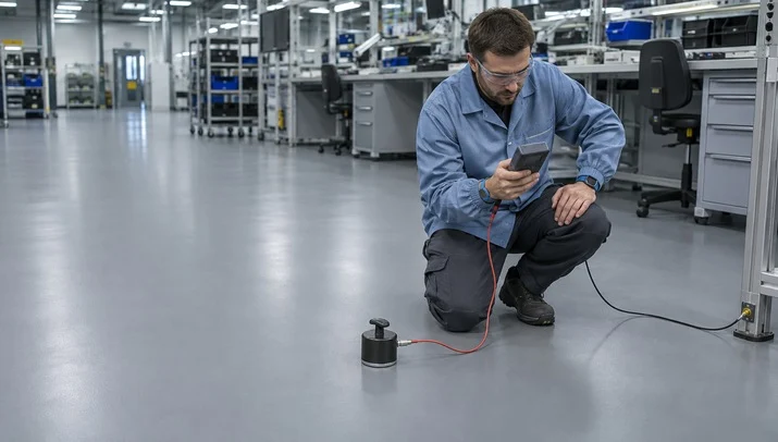
EN 1081 sets the method for measuring the electrical resistance of resin floor finishes. BS EN 61340-4-1 covers installed floors in ESD work. Both measure resistance to earth using weighted tripod electrodes at a defined test voltage. Testing confirms performance across every square metre, not just one sample panel.
The test applies a direct-current voltage across the cured surface and records resistance in ohms. Conductive finishes normally return values below 1 × 10⁶ Ω. Dissipative finishes sit between 1 × 10⁶ Ω and 1 × 10⁹ Ω. That upper band bleeds charge away without the floor acting as an active conductor.
Charge Decay Rates and Human Body Voltage
Performance depends on how fast accumulated voltage drains from personnel into the earthing system. BS EN 61340-5-1 requires the combined floor and footwear system to hold human body voltage below one hundred volts. Meeting that figure needs controlled decay, avoiding both charge build-up and high-current transfers.
Decay time measures the fraction of a second needed for voltage to fall to a safe baseline. Solvent handling demands near-instant drainage to prevent incendiary sparking. Electronics cleanrooms want a slower rate over several tenths of a second. That rate avoids current surges through ground pins whilst keeping voltage under component thresholds.
Did You Know?
DSEAR came into force on 9 December 2002 and requires duty holders to control every ignition source inside a classified zone, static discharge included. Enforcement sits under the Health and Safety at Work etc. Act 1974. Offences tried on indictment in the Crown Court carry an unlimited fine and up to two years’ imprisonment.
Hazards Created by Over-Specified Conductivity
Shock Risk in Maintenance and Switchroom Areas
An overly conductive floor creates real danger where staff use powered tools or open control panels. If an operative touches a live conductor whilst standing on that surface, their body becomes the path to earth. The floor that protects a microchip can therefore put a technician at risk.
BS 7671 and IEC 60364-4-41 take the opposite approach in non-conducting locations. Resistance to earth must exceed 50 kΩ up to 500 V, and 100 kΩ above it. Installing conductive resin in a switchroom works directly against that principle. From experience across the sector, this clash is the specification error we are asked to correct most often.
Installation Cost and Carbon Additive Loads
Conductive grades carry higher loadings of carbon fibre, graphite or metal particulate to reach very low resistance. Those additives raise material cost and change how the resin handles during application. Specifying a conductive build where a dissipative one would pass wastes budget on every square metre laid.
Carbon loading also darkens the cured colour. Light pastel shades become unachievable at high additive ratios. Cleanrooms that rely on high light reflectance lose that benefit. Matching the resistance band to the actual hazard keeps both cost and lighting performance under control.

Need a Resin Flooring Site Visit and Quote?
System Engineering and Grounding Protocols
Copper Grid Networks and Earthing Terminals
A static control floor only works once it reaches a verified earth terminal. Installers lay copper grid tape across the prepared substrate before the conductive primer and wearing screed go down. That metallic network gives accumulated charge a low-resistance route away from the walking surface.
An unearthed conductive floor is simply an isolated conductor holding charge. A qualified electrical contractor must bond the perimeter copper tails to the building earthing bar. Those connections are certified before resistance testing begins. Every bay and room boundary needs its own connection point, including across expansion joints and partitions.
Resin Chemistry and Carbon Fibre Additives
Manufacturers disperse carbon fibre, fine metal strands or speciality salts through the liquid binder. This builds a continuous conductive matrix inside finishes from FeRFA Type 3 coatings to Type 8 heavy-duty screeds. Additive ratios must stay precise, or the floor loses either electrical performance or mechanical strength.
Poor dispersion during mixing leaves dead spots across a finished bay. Excess loading makes the resin viscous and stops it self-smoothing, which brings pinholing and surface defects. Factory pre-batched units give consistent volume resistivity. They also hold compressive strength, chemical resistance and tolerance of heavy forklift traffic.
Case Studies
Our case studies cover – Printing & Packaging, Warehousing & Logistics, Pharma & Healthcare, Automotive & Engineering, Aviation & Aerospace, Food & Drink, Printing & Packaging, Warehousing & Logistics, Pharma & Healthcare
Operational Factors Beyond the Floor Finish
Dissipative Footwear and Personnel Grounding
A compliant floor cannot drain charge from an operative wearing insulating soles. Standard rubber and synthetic footwear breaks the path between the person and the earthed resin completely. Floor and footwear have to be treated as one protective system, specified and audited together.
BS EN 61340-5-1 audits test the combined resistance of person, footwear and floor. Sites must issue certified ESD shoes or heel grounders to staff and escorted visitors entering a designated zone. Without that control, even the best resin installation delivers nothing measurable.
Humidity Control in Cleanrooms and Dry Plant
Relative humidity drives both charge generation and surface dissipation. Below thirty per cent, triboelectric charging accelerates and personnel build high voltages during ordinary movement. A specified floor must hold its resistance band through seasonal humidity swings, not only on the day of commissioning.
Semiconductor suites and packing halls run HVAC at deliberately low moisture levels. Humidity-dependent finishes drift outside their compliance band in those conditions. Carbon-loaded conductive and dissipative matrices rely on an embedded physical network rather than surface moisture. That is why we specify them for conditioned spaces.
“JD Flooring did an excellent job installing a resin floor in our food production facility. The floor is durable, hygienic, and meets all safety regulations. The team was knowledgeable and professional, and the project was completed within the agreed-upon timeframe. I highly recommend JD Flooring for food industry flooring needs.”
Alex Martinez
Routine Verification and Lifecycle Maintenance
Resistance Audits and Scheduled Retesting
Commissioning requires documented resistance tests before handback, followed by annual condition surveys. Auditors use high-resistance megohmmeters with concentric ring or point-to-point electrodes to confirm the band. That record is the evidence a duty holder relies on during enforcement or insurance scrutiny.
Testing must cover transit routes, forklift lanes and operative workstations rather than one convenient point. Resistance drifts as rolling loads abrade the topcoat and dirt collects in textured finishes. Logging each reading in the health and safety file keeps the installation demonstrably compliant.
Cleaning Regimes and Surface Contamination
The wrong cleaning product ruins electrical performance faster than wear ever will. Conventional wax and acrylic polish leave an insulating film that blocks the conductive path. Floors that passed at handover then fail retest. Maintenance teams must use approved pH-neutral detergents at the correct dilution.
Scrubber-dryers need non-abrasive pads matched to the finish. Aggressive pads scratch the topcoat and expose carbon fibre unevenly, producing unpredictable local resistance spikes. Oil, grease and abrasive dust must be removed promptly. Clean contact between footwear and the resin matrix is what makes the system work.
Calculate The True Cost
A three day shutdown at a plant turning over £2,000 an hour is £120,000 of lost output. On most sites that is several times the cost of the new resin floor installation. We have developed our own free custom calculator top help you calculate the true cost and a new resin floor.
Selection Strategy for Industrial Facilities
Zoned Boundary Assessment Across Production Areas
Correct specification starts with a map of process risk, zone by zone. DSEAR assessments fix the boundaries where vapour or dust demands rapid earthing. Adjacent warehousing and test suites need different resistance profiles. A single uniform specification across a whole plant is both technically wrong and expensive.
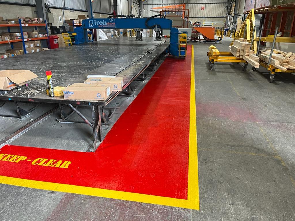
Graded specification is the practical answer on large sites. Heavy-duty conductive screed goes into solvent mixing bays. Dissipative coatings cover dry assembly aisles at lower cost. Demarcated transition lines then tell staff exactly where footwear rules and handling protocols change.
Conductive Versus Dissipative Flooring in Practice
Choosing between conductive versus dissipative flooring comes down to one question. Is the dominant hazard ignition of an explosive atmosphere, or failure of a sensitive component? Conductive finishes clear charge below one megohm. Dissipative finishes bleed it between one megohm and one gigohm, keeping operatives out of circuit.
Involve a resin specialist before construction, not after the slab is poured. Mechanical traffic, chemical exposure and washdown regimes all shape the system build. The right FeRFA specification carries forklift point loading and aggressive cleaning agents whilst holding its verified resistance.
Final Thoughts
Work backwards from the hazard, not forwards from a datasheet. Conductive flooring is the right answer in solvent handling and powder processing, where charge must reach earth immediately. Deploy the same system across general electronics assembly and you add cost whilst creating a shock risk. Fixed resistance targets, taken from the published standards, settle the question before procurement starts.
Automated handling and tighter component tolerances will narrow the acceptable resistance window further. ATEX and DSEAR scrutiny continues to sharpen across UK processing sites. Floor specification will stay a foundation decision rather than a finishing detail.
Arrange a Free Site Survey
If you are thinking about upgrading the flooring in your commercial or industrial space then we would love to hear from you. Our team of experts will conduct a free onsite survey and then guide you through the process of product selection and project planning, whilst remaining mindful of your budgetary restraints.
Frequently Asked Questions
A:
Conductive finishes hold resistance below one megohm, so charge reaches earth almost instantly. That speed matters in DSEAR and ATEX zones, where a small spark can ignite vapour or combustible dust. Dissipative finishes sit between one megohm and one gigohm. They bleed charge away gently, which protects sensitive electronic components from sudden current transfer. The higher band also keeps personnel out of the current path when they work near live low-voltage equipment.
A:
The standard sets resistance to earth below 1 × 10⁹ ohms for floors inside an ESD protected area. Where the floor and footwear work together as the grounding route, the combined system must keep human body voltage below one hundred volts. Those two figures are tested together, not separately. Meeting both prevents latent electrostatic damage during assembly, test and packing in precision electronics, aerospace and defence facilities.
A:
No. An ungrounded conductive floor behaves as an isolated conductor. It collects charge with nowhere to release it, which can leave the situation worse than an insulating surface. Installers lay a continuous copper tape grid across the prepared concrete before the conductive coats go down. A competent electrical contractor then bonds the copper tails to the building earthing system. Resistance testing follows that connection and confirms a continuous discharge route.
A:
Wax and acrylic polish lay an insulating film over the conductive matrix. That film breaks contact between footwear soles and the embedded carbon fibre. A floor that passed at handover will then fail its next resistance test. Sites need a dedicated maintenance regime using approved pH-neutral detergents at the stated dilution. Those products clean without leaving residues, waxes or film-forming sealants behind. Cleaning contractors should be briefed on the restriction.
A:
No, the two specifications are opposites. A cleanroom or data hall needs a surface that moves charge away from sensitive equipment. A switchroom needs the reverse. BS 7671 and IEC 60364-4-41 treat it as a non-conducting location, with resistance to earth above 50 kΩ up to 500 V and above 100 kΩ beyond that. The insulating floor deliberately blocks current flow and protects technicians during live maintenance.
