
Static Dissipative Flooring and EN 1081 Testing
Static dissipative flooring is an electrical component, not a decorative finish. In plants handling microelectronics, solvents or fine powders, an uncontrolled spark carries real cost. A correctly engineered resin system bleeds charge across its matrix and into an earthing network. Specifiers must balance that electrical performance against mechanical wear.
How does a facility prove that its floor meets the thresholds demanded by electronics, pharmaceutical or explosive environments? Which test methods, earthing details and housekeeping rules keep that performance stable for the life of the floor?
Key Takeaways
- Static dissipative floors hold electrical resistance between one megohm and one billion ohms, bleeding charge to earth without sparking.
- Standard EN 1081 measures surface, vertical and earth resistance using a weighted tripod electrode with conductive rubber feet.
- Installers bond a copper tape grid to the substrate, then overlay conductive primer before any dissipative topcoat goes down.
- ATEX and explosives areas need lower resistance windows than electronics assembly, so resin formulation changes with the hazard.
- Insulating footwear and conventional floor polish both defeat a compliant floor, so housekeeping forms part of the specification.
Electrical Resistance Bands and Floor Classifications
Flooring classification rests on measured electrical resistance, not on trade descriptions. Conductive, dissipative and insulating surfaces each serve a different hazard. A specifier must fix the target resistance window before anyone selects a resin. That figure then drives primer choice, earthing design and the maintenance regime agreed with the facilities team.
The table below sets out the resistance bands used across BS EN 61340-5-1, EN 1081 and IEC 60364. Each band carries a different earthing requirement and a different test voltage. Match the room function to the correct band first. The commonest specification error is a conductive floor inside a switchroom.
| Floor Classification | Electrical Resistance Window | Governing Standard | Typical Application |
|---|---|---|---|
| Conductive flooring | 10,000 to 1,000,000 ohms | EN 1081 and IEC 61340-4-1 | ATEX zones, munitions handling |
| Static dissipative flooring | 1,000,000 to 1,000,000,000 ohms | BS EN 61340-5-1 and EN 1081 | Electronics assembly, cleanrooms |
| Explosives handling floor | Below 50,000 ohms | EN 1081 and sector rules | Pyrotechnics, propellant manufacture |
| Insulating floor, up to 500 volts | Above 50,000 ohms | IEC 60364 | Low-voltage electrical switchrooms |
| Insulating floor, above 500 volts | Above 100,000 ohms | IEC 60364 | High-voltage plant and substations |

Static Control Categories and Resistance Windows
Dissipative Floors Against Conductive Floors
A dissipative floor bleeds charge to earth at a controlled rate. A conductive floor drains it almost instantly. Conductive systems sit below one megohm. Dissipative systems sit between one megohm and one billion ohms under BS EN 61340-5-1. The slower route protects microchips from sudden high-current discharge during assembly.
In practice, the choice follows the hazard rather than the product name. Electronics assembly areas take a dissipative rating. Solvent and munitions areas take a conductive rating. Suppliers often market both under a single ESD banner. A specification should therefore quote the resistance window and the governing standard, not the trade term.
ESD Floors Against Insulating Switchroom Surfaces
Electrical safety pulls in the opposite direction inside a switchroom. Static control areas need a path to earth. High-voltage plant rooms need the floor to block one. IEC 60364 sets insulating floor resistance above fifty thousand ohms for systems up to 500 volts. Above 500 volts the figure rises to one hundred thousand ohms.
A dissipative floor inside a switchroom creates a genuine shock risk. It offers stray current an earth path through the technician. The reverse error is just as costly. An insulating floor inside a cleanroom lets charge build on operators and equipment. Facilities teams should assess each room on its function alone.
EN 1081 Test Methods and Equipment
Tripod Electrode Geometry and Contact Resistance
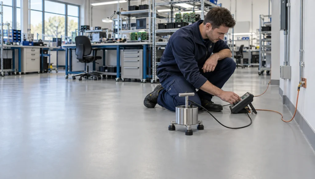
Standard EN 1081 calls for a weighted tripod electrode. Three conductive rubber feet carry carbon loading and flex into the surface profile. The applied load standardises contact resistance before the technician records a reading. Technicians place the feet on the resin without piercing the film, which keeps results repeatable across textured finishes.
From experience across the sector, contact quality decides whether a floor passes or fails on the day. A dusty surface raises the reading. A damp one lowers it. Each foot must sit flat on the finished resin. Teams clean and dry the test points first, then let the electrode settle before recording.
Test Procedures for Surface and Earth Resistance
EN 1081 separates three measurements. Surface resistance runs between two electrodes placed on the floor. Vertical resistance runs down through the system. Resistance to earth runs from the surface to the building earthing terminal. Test voltage follows the expected band, with lower voltages used on conductive floors.
Technicians test conductive floors at one hundred volts direct current. Dissipative floors require five hundred volts. Technicians work to a grid pattern rather than a convenient corner. They record minimum, maximum and geometric mean values. A single compliant reading proves very little, since dead spots appear where primer coverage thinned during installation.
Did You Know?
BS EN 61340-5-1 treats the operator, the footwear and the floor as one system. That system must measure below one billion ohms to ground. Body voltage must stay under one hundred volts. A floor that passes in isolation can still fail once operators step onto it.
Copper Earthing Grid Design and Connection Details
Grid Spacing and Conductive Primer Placement
The conductive layer sits beneath the visible floor. Installers grind the concrete to remove laitance, then vacuum the slab. Self-adhesive copper tape goes down in an interconnected grid, usually spaced between two and five metres. A carbon-loaded primer then bridges the gaps and forms a continuous plane across the substrate.
Grid spacing is not arbitrary. Every square metre of finished floor must reach copper through the primer. Wider spacing leaves high-resistance pockets that only appear at commissioning. In practice, we find that tape runs should follow the bay layout. That keeps the grid clear of expansion joints and future plinth positions.
Terminations at Facility Earth Points
Copper tape must terminate somewhere real. Installers carry the tape up the perimeter wall into surface-mounted terminal boxes. A qualified electrician then bonds each terminal to a clean earth point rather than structural steel. Site ESD control plans often call for a protective resistor at the connection.
An ungrounded conductive floor holds charge with nowhere to send it. That is the single most common defect we see on handover. Two terminals per floor plate give redundancy if one connection loosens. The electrician should test continuity at each point and record the figure. Structural steel carries electrical noise and can disturb sensitive instrumentation.

Need a Resin Flooring Site Visit and Quote?
Target Resistance Profiles by Industrial Sector
Electronics Assembly and Cleanroom Environments
Electronics plants work to BS EN 61340-5-1 and keep resistance to ground below one billion ohms. These electrostatic protected areas guard microprocessors against low-voltage damage. Cleanrooms add a second demand. The resin must stay seamless and non-porous so that it sheds no particulate into the air classification.
These two demands pull against each other. Semiconductor fabrication runs dry, and low humidity raises surface resistance. High-build dissipative epoxy handles that better than thin coatings. The finish must also survive aggressive cleaning agents without losing conductivity. A stable dissipative surface stops static fields attracting airborne particles onto work in progress.
Explosives Manufacturing and ATEX Zoned Areas
Explosives and solvent handling need a conductive band, not a dissipative one. Typical targets fall between ten thousand and one million ohms. Energetic materials areas often demand below fifty thousand ohms. The aim is simple. Charge must drain faster than it can build into an incendive spark.
DSEAR 2002 places statutory duties on UK employers to control ignition sources in zoned areas. Static discharge counts as an ignition source for vapours, gases and combustible dust. Munitions factories, solvent decanting bays and powder mixing suites all fall inside that duty. Conductive resins use heavier carbon fibre loading to reach the lower targets.

Case Studies
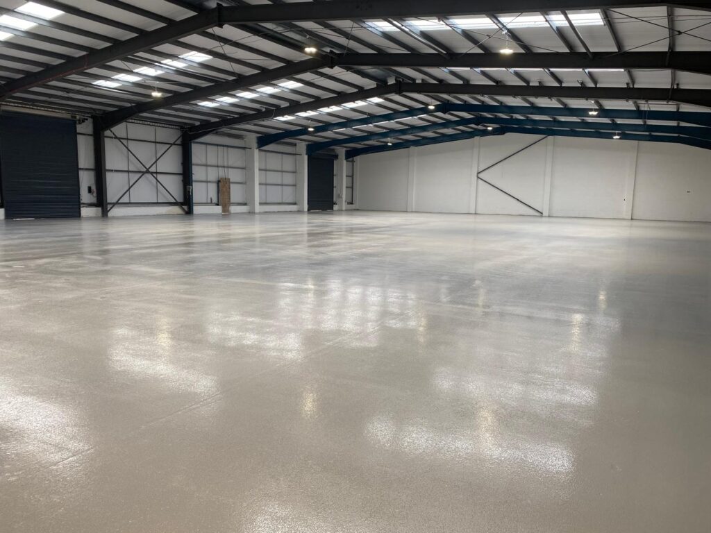
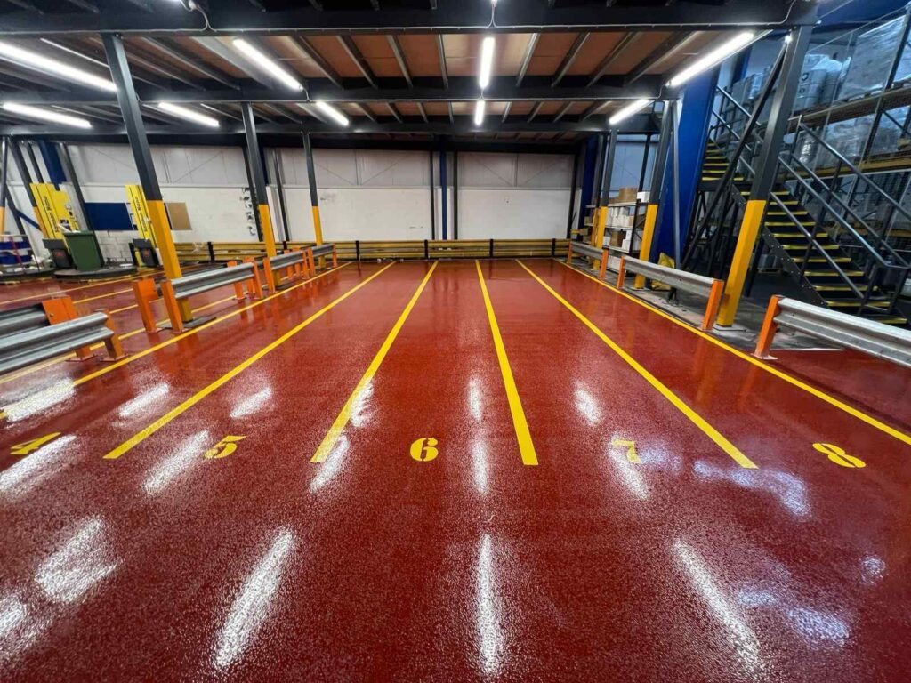
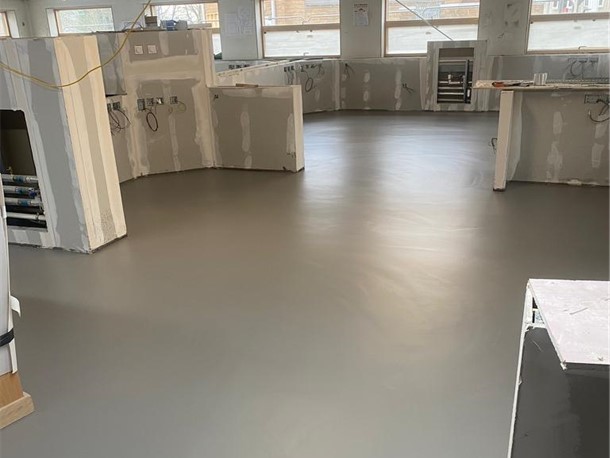
Our case studies cover – Printing & Packaging, Warehousing & Logistics, Pharma & Healthcare, Automotive & Engineering, Aviation & Aerospace, Food & Drink, Printing & Packaging, Warehousing & Logistics, Pharma & Healthcare
Verification Protocols and Site Acceptance Testing
On-Site Earthing Verification Method
Site acceptance proves continuity between the finished surface and the building earthing busbar. Technicians measure from random floor points back to the nearest copper terminal. A common pattern is five test points for every hundred square metres. Point-to-point readings across adjacent bays confirm that the primer plane carries charge laterally.
Testing should happen before the floor goes into service, not after a failure. Engineers log every reading against a floor plan. That record becomes the baseline for later audits. Where a reading falls outside the window, the installer can still open the area and correct the primer. Once production starts, that option disappears.
Environmental Factors During Site Assessment
Humidity and temperature move the numbers. Dry air raises surface resistance on synthetic resin, and a winter commissioning test reads higher than a summer one. Engineers must log relative humidity and substrate temperature alongside every resistance value. Without that record, nobody can defend the compliance data in a dispute.
Surface moisture assists charge transfer, which is why readings drift with the seasons. BS EN 61340-4-1 sets a low-humidity conditioning regime at twelve percent relative humidity for severe cases. Few sites can replicate that on a live floor. Recording ambient conditions at the time of test is the practical alternative. That record settles most handover arguments.
“JD Flooring did an excellent job installing a resin floor in our food production facility. The floor is durable, hygienic, and meets all safety regulations. The team was knowledgeable and professional, and the project was completed within the agreed-upon timeframe. I highly recommend JD Flooring for food industry flooring needs.”
Alex Martinez
Footwear Performance and Housekeeping Protocols
Combined Personnel and Footwear Resistance Values
A static control floor only works as part of a system. The operator, the footwear and the resin form a single electrical path. Standard safety boots carry thick insulating outsoles. Those outsoles break the path and strand the charge on the person, whatever the floor measures in isolation.
Walking generates charge through triboelectric contact, and an ungrounded operative can carry thousands of volts. Certified ESD footwear or heel grounders complete the circuit. Entry-point test stations verify each person at the start of a shift. In practice, we find footwear discipline fails long before the resin does. Audit records should cover both.
Contamination Risks and Floor Polish Hazards
Incorrect cleaning is the leading cause of premature static control failure. Conventional acrylic polish dries into an insulating film across the resin pores. Resistance rises immediately, and the floor fails its next test. Dust, grease and particulate build-up raise contact resistance by the same mechanism, though more slowly.
Facilities teams need a written cleaning schedule tied to the floor specification. Approved ESD agents are pH-neutral and leave no dielectric residue. Rotary scrubber-dryers lift contamination that mopping simply spreads. Contract cleaners should receive the product list in writing. One shift with the wrong product can undo a compliant installation.
Calculate The True Cost
A three day shutdown at a plant turning over £2,000 an hour is £120,000 of lost output. On most sites that is several times the cost of the new resin floor installation. We have developed our own free custom calculator top help you calculate the true cost and a new resin floor.
Specification Choices for Resilient ESD Floors
Slip Resistance Alongside Static Control
Static performance and wet slip safety can work against each other. Coarse aggregate adds traction but interrupts the conductive path through the resin. Fine, carefully graded aggregate keeps both properties intact. Under BS 7976 pendulum testing, a Pendulum Test Value of thirty-six or above represents low slip potential.
Wet process areas force the issue. A dissipative floor that nobody can walk on safely is not fit for purpose. Formulators blend conductive fillers with graded aggregate to hold both figures. The specification should state the target pendulum value and the target resistance together. Testing both at handover avoids an argument later.
Scheduled Monitoring and Resistance Audits
Electrical performance drifts over a working life. Forklift traffic, chemical contact and surface wear all alter the resin matrix. An annual audit with calibrated EN 1081 equipment catches high-resistance patches early. Facilities managers should run that audit alongside the slip resistance survey and file both results together.
A commissioned floor is not a finished matter. Resistance logs build an audit trail for quality certifiers and insurance underwriters. They also show whether a patch repair held. Where readings climb year on year, the cause is usually housekeeping rather than wear. The log makes that distinction visible.
Final Thoughts
Static dissipative flooring is an electrical circuit built into the building fabric. Substrate preparation, copper grid, primer, topcoat and earthing terminal all carry part of the duty. One weak link voids the rest. Testing under EN 1081 and BS EN 61340-5-1 confirms that the finished system holds its design window.
Process sensitivity keeps rising across microelectronics, pharmaceutical manufacture and chemical processing. The floor must keep pace with it. Resin chemistry, ambient conditions, footwear and cleaning products interact continuously. A facility that logs all four holds defensible evidence of control, year after year.
Arrange a Free Site Survey
If you are thinking about upgrading the flooring in your commercial or industrial space then we would love to hear from you. Our team of experts will conduct a free onsite survey and then guide you through the process of product selection and project planning, whilst remaining mindful of your budgetary restraints.
Frequently Asked Questions
A:
Conductive floors measure below one megohm and drain charge almost instantly. They suit ATEX zones and explosives handling, where a spark is the primary risk. Static dissipative floors measure between one megohm and one billion ohms. They bleed charge away at a controlled rate instead. That slower route protects microchips and circuit boards from sudden high-current discharge. The site risk assessment decides which band applies, not the product brochure.
A:
EN 1081 covers resilient, resin and modular floor coverings. It measures surface resistance, vertical resistance and resistance to earth. The method uses a weighted tripod electrode with conductive rubber contact pads. Those pads simulate the contact area of footwear on the finished surface. Readings show whether charge can travel across the floor and down through the resin into the earthing system. Test voltage varies with the expected resistance band.
A:
Engineers first confirm continuity between the exposed copper terminals and the building main earthing terminal. They then take point-to-ground readings at several locations using an insulation tester and a weighted tripod electrode. Each reading proves that current travels from the resin surface into the copper grid. The path runs through the conductive primer and out to the building earth. The commissioning certificate records those figures alongside ambient temperature and relative humidity at the time of test.
A:
An ESD floor works as a system made up of the resin, the earthing grid and the operator. Standard safety boots use thick insulating rubber or polyurethane outsoles. Those outsoles block the electrical path to the floor. Charge generated by movement then stays on the person and their clothing. BS EN 61340-5-1 requires certified ESD footwear or conductive heel grounders. That keeps the path unbroken from operator to earth.
A:
No. Conventional waxes, sealers and polishes dry into an insulating polymer film across the surface. That film blocks contact with the conductive resin beneath it. The floor then fails its next resistance test, even though nothing about the resin has changed. Cleaning should use dedicated ESD products and pH-neutral detergents that leave no dielectric residue. Contract cleaners need that product list in writing before they start work on site.
